The Network Layers Breakdown
Reading: chapter: 7.2, Lec17, Chapters 17-18 of the 6.02 notes, Chapter 19 of the 6.02 notes.
network layers
organization
Principle: adopt sweeping simplifications, networks are organized as layers (layering of protocols).
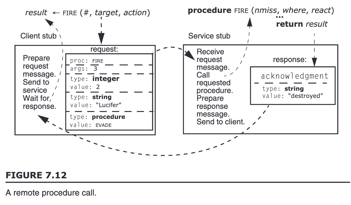
three-layer reference model example: a defense program has a procedure call and the procedure for single user.
-
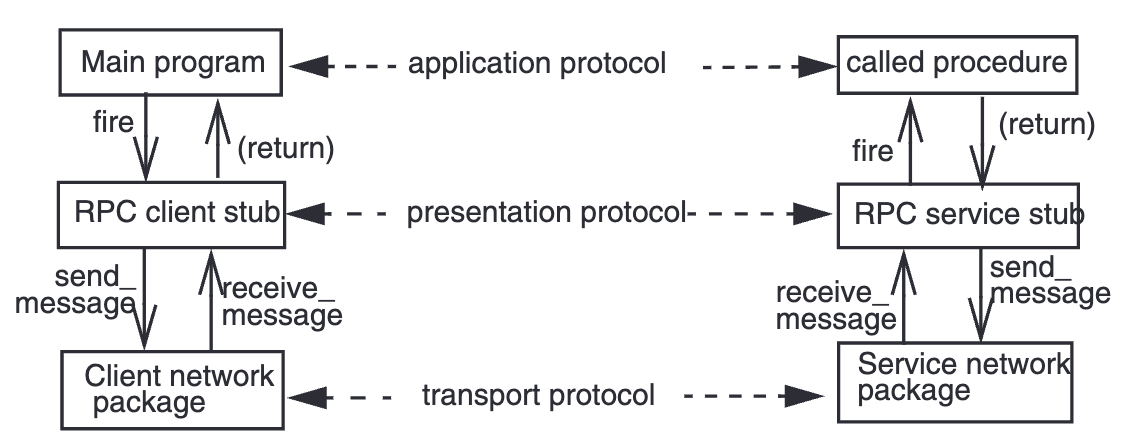
protocols involved in this example
-
protocol between client stub and service stub / the main program and the procedure it calls
-
remote procedure call (RPC) protocol -> improvement: convert single user -> multiuser by RPC
-
-
Send/receive message to/from network -> add a transport layer to communicate
-
-
-
In usual layered organizations, a module has two interfaces. A network module has three (transport + presentation (data format, semantics) + application).
-
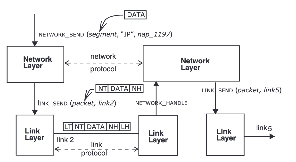
Layered design: Each layer provides an interface to the layer above and hides interfaces below.
-
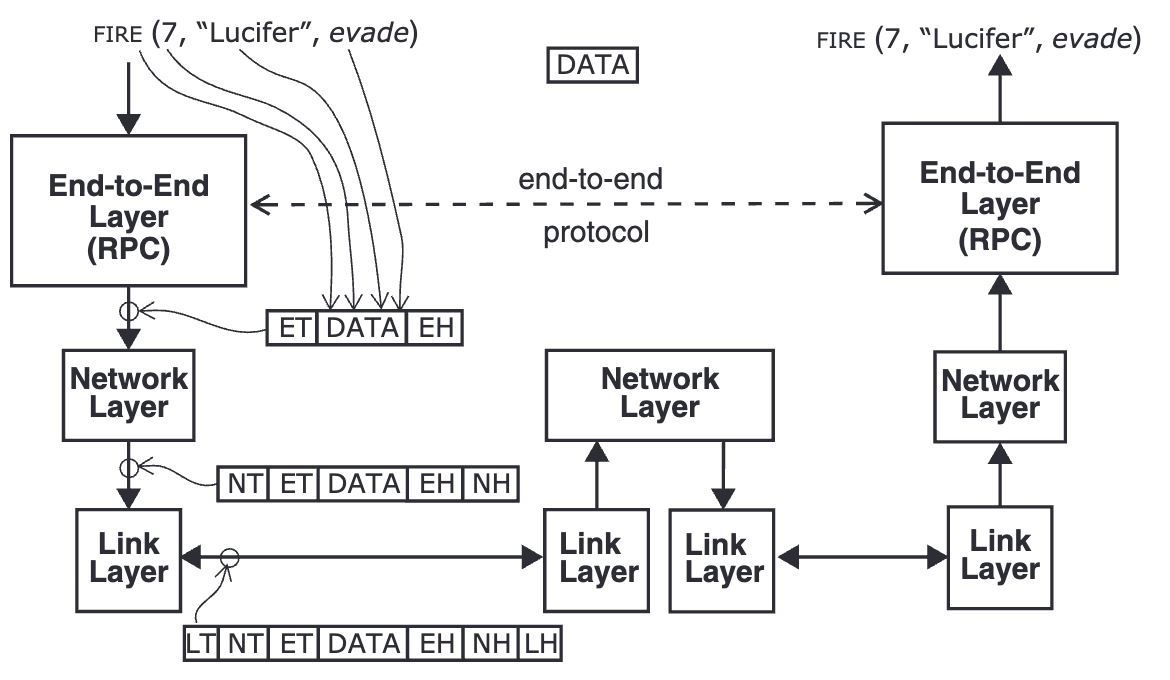
Layers are abstracted as three parts: end-to-end layer, network layer, link layer. Application layer is not included.
- Data flow from top down: message/stream -> segments -> packets -> frames
- data sent from upper layer to the lower layer is called
payload. The lower layer attached aheaderandtrailerto the front and end of the data so the corresponding lower layer can process. That’s why layers can hide
- data sent from upper layer to the lower layer is called
- link layer: packet switched network, send the bits of the packet across one link. Ex: ethernet, wifi, bluetooth
- network layer: deliver a segment from the source to the destination. Ex: IP
-
- Data flow from top down: message/stream -> segments -> packets -> frames
end-to-end layer
Each layer considers the payload transmitted by the layer above to be information that it is not expected, or even permitted, to interpret.
Problems: Why the end-to-end layer is an unstructured library of service modules?
Different applications have a wide range of requirements for services and any lower layer decision in one app can be counterproductive fro at least some apps.
-
RPC provides services hiding underlying network aspects from its app
-
presentation services: change data formats and semantics
-
transport services: streams/messages -> segments with lost, duplicated, out-of-order segments.
-
session services: search, handshake, …
-
-
Open Systems Interconnect has seven layers. The additional layers are:
-
link layer -> strategy layer (data link layer) + physical layer
-
end-to-end layer -> application + presentation + transport + layer providing the session services
-
the end-to-end argument
Principle: the end-to-end argument: the application knows best. Don’t bury it in a lower layer, let the end points deal with it because they know best what they need.
Example: file transfer and checksum
When sending a file from A to B, B will recalculate the checksum anew after receiving the file to verify a complete delivery (application layer checksum).
Given the end-to-end approach, oen can add a link-layer checksum. This additional check does not eliminate the application layer check but can act as a performance enhancement for it observes failure sooner.
mapped and recursive apps
Decomposition a network has two forms: maaped, recursive.
-
mapped composition: build network layer A on network layer B by mapping high-layer addresses to lower-layer network addresses.
- example: Appletalk (add a better network technology), Internet protocol (internetworking)
-
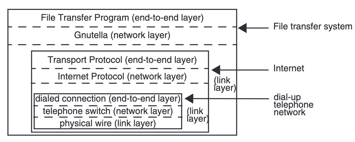
recursive composition: a three-layer network rests on a link layer of another network
- example: tunnel (+encryption = VPN), overlay network
-
-
The Internet links many network layers by mapping them all to a universal network layer using IP.
- end-to-end protocols: TCP, UDP, RTP…
- application protocols: FTP (file transfer), HTTP (www), SMTP, POP (mail dispatch and pickup), IRC (text messaging), VoIP (telephone), Gnutella, bittorrent (file exchange)…
olc
- protocol is a fancy name of contract for networks as spec for programming languages. It achieves agreements on the calling function and called one.
- IP is in the network layer. TCP is in a layer above IP.
packet switching
Takeaways from Lec17 packet switching:
-
packet switched network:
- design objective: efficiency and reliabilty
- use address on the message
- break down big source data to small packets
- communication link is associated with an address.
- packet is an atomic unit of delivery. It consists of a link (source addr, destination addr) and message (bits).
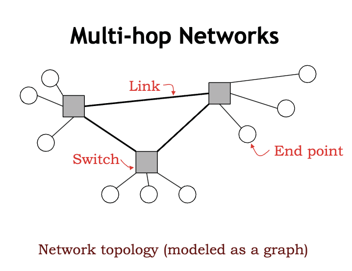
- network topology
- a simplified network
-
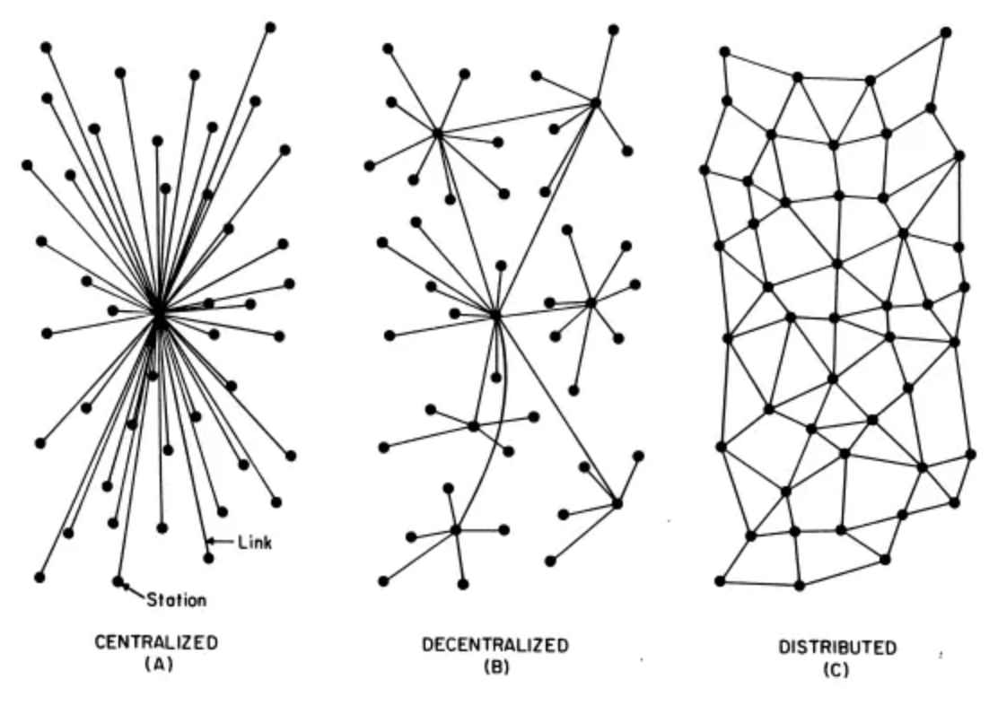
- 1964, distributed communication network
-
- a simplified network
- design objective: efficiency and reliabilty
-
statistical multiplexing: when too many packets come to a switch and exceed its receiving limit, it waits in queue. If queue is full, then the switch just drop the packet and let the end point deals with.
-
queue adds latency of data transmission.
-
It is better to store the packet inside switch which piles up tasks exceeding current processing limit of a switch
-
multiplexing/demultiplexing
-
-
-
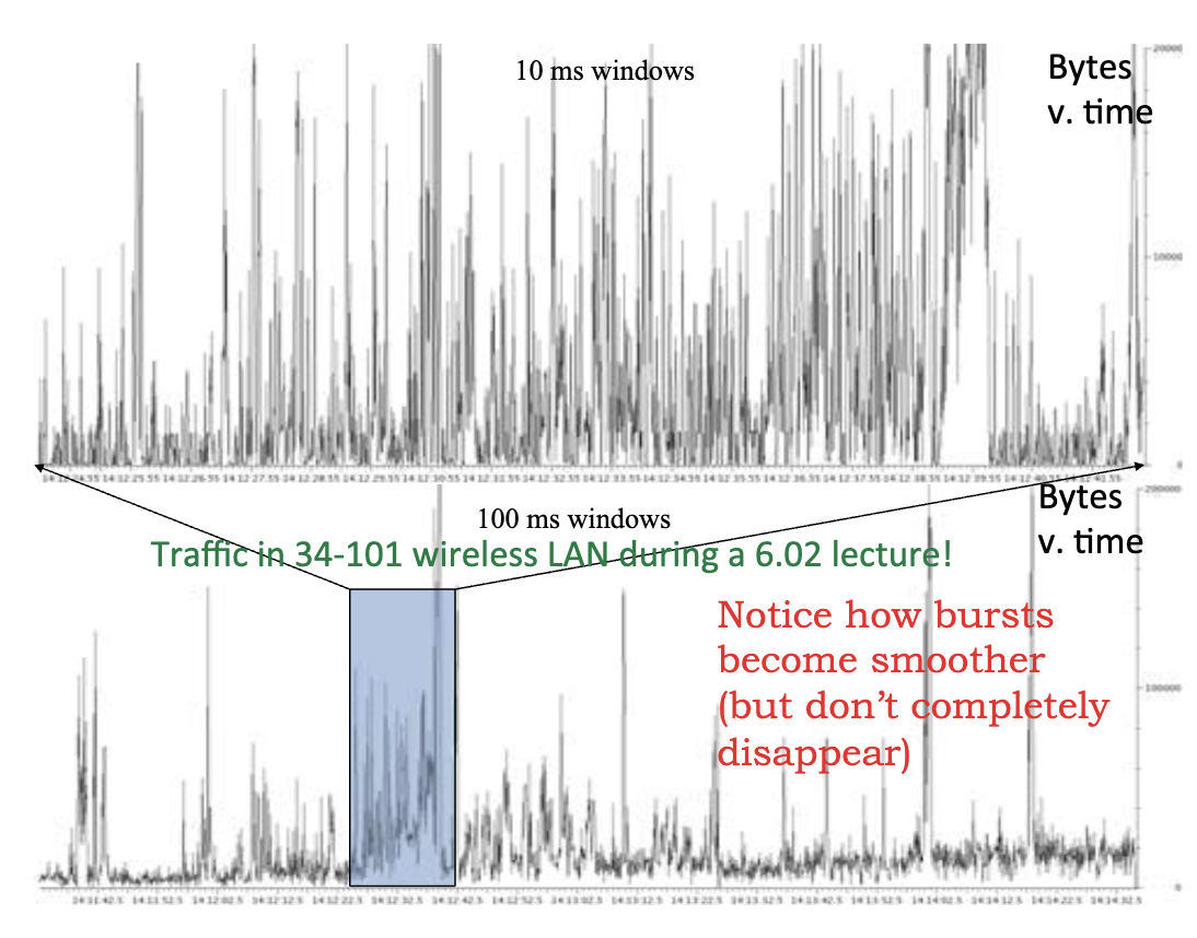
Real life traffic is like temporarily burst to 10 times of average bit rate.
-
- A malicious virus example is DDOS attack on websites, that is a large amount of accessing the service out of limit of websites.
-
-
Bandwidth is in terms of Herz. If it’s v, it refers to a range of frequencies of data transmission around the value v.
-
Evaluation standards of network are: 1) rate of link, 2) delay (or latency)
- propagation delay: time to send one bit
- transmission delay: time to send size L bits over a link with bit rate c, L/c. It’s also the time from the first bit to the last bit arriving at the switch.
- processing delay: host and switch deal with packet (header, checksums)
- queueing delay: time spent waiting in queue
